

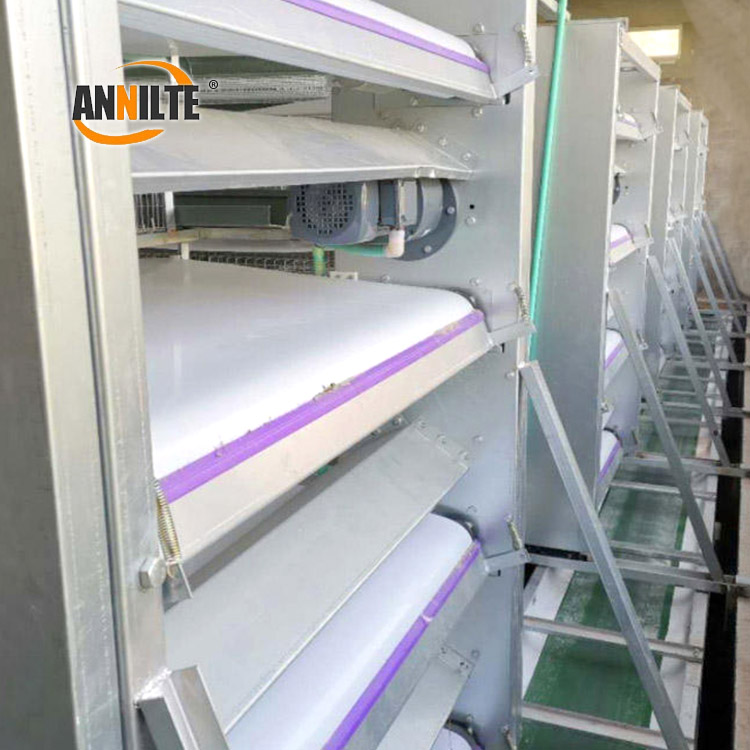
A poultry manure belt, also called a chicken manure removal belt or manure conveyor belt, transports manure from beneath the cage rows to the cross conveyor or manure removal point. Correct installation is essential for reliable tracking, clean discharge, low mechanical load, and stable operation.
The exact installation method depends on the cage system, belt material, drive arrangement, splice design, and take-up mechanism. This guide is intended for common flat-belt manure removal systems. Always confirm belt dimensions, splice parameters, tension requirements, and machine-specific procedures with the equipment manufacturer or belt supplier before installation.
Quick answer: how is a manure belt installed?
A safe installation normally follows this sequence:
- Confirm the belt and cage-system specifications.
- Isolate all energy sources and clean the belt path.
- Record the original belt routing before removing the old belt.
- Inspect the drive pulley, tail pulley, return rollers, bearings, frame, and scraper.
- Feed the new belt through the system without twisting it.
- Complete the approved splice or mechanical connection.
- Apply initial tension gradually; do not overtighten.
- Jog the system at low speed and check tracking, splice passage, and side clearance.
- Run the belt empty before carrying out a gradual loaded test.
- Recheck the scraper, transfer point, guards, and emergency-stop function.
1. Prepare before installation
Confirm the belt specification
Before removing the existing belt, confirm the following information:
- Belt material, such as PP, PVC, or another specified belt compound;
- Belt width, length, thickness, and surface structure;
- Whether the belt has a guide strip, tracking rib, or other locating feature;
- Belt running direction and drive-pulley location;
- Cage configuration, number of tiers, and manure discharge direction;
- Connection method: hot welding, finger splice, diagonal splice, overlap splice, or mechanical fastener;
- Compatibility of the scraper, return rollers, pulleys, and take-up system.
Do not size the replacement belt only by looking at the old belt. An old belt may have stretched, narrowed, worn at the edges, or changed length during service. Compare the old belt with the equipment drawing and take accurate field measurements.
Inspect the installation area
Before fitting the new belt, make sure that:
- The drive motor and related conveyors are shut down and isolated;
- The belt path is free from hardened manure, wire, bolts, weld spatter, stones, and other debris;
- The drive pulley, tail pulley, and return rollers rotate freely;
- Pulley surfaces are free from sharp burrs, deep damage, and excessive buildup;
- The frame, side plates, supports, and roller mounts are not visibly distorted;
- The scraper edge is straight and not excessively worn;
- The belt path has sufficient clearance on both sides.
A new belt will not correct a seriously misaligned frame or non-parallel pulleys. Resolve those mechanical issues first.
Prepare tools and personal protective equipment
Typical tools include measuring equipment, cleaning tools, wrenches, screwdrivers, temporary clamps, the approved splicing equipment, and the machine's take-up adjustment tools.
Use cut-resistant gloves, safety footwear, and eye protection. If hot welding is required, use heat-resistant protection and provide suitable ventilation. Follow the farm's site safety rules and the belt supplier's installation instructions.
2. Step-by-step manure belt installation
Step 1: Shut down, isolate, and clean the belt path
Stop the manure belt and any connected cross conveyor. Isolate electrical and mechanical energy using the site's lockout/tagout (LOTO) procedure in North America or the equivalent energy-isolation procedure required at the site in Europe. Verify that the drive cannot start unexpectedly and that moving parts have stopped completely.
Remove manure buildup, litter, wire, fasteners, and any other foreign material from the belt channel. Never place a hand near a pulley, chain, roller, or belt underside while the equipment can still start.
When several people are working, appoint one person to control communication, re-energization, and testing.
Step 2: Document the original belt routing
Before removing the old belt, take clear photographs and note:
- How the belt passes around each pulley;
- The direction of any guide strip or tracking rib;
- The original splice location and orientation;
- The initial position of the take-up mechanism;
- The direction and contact position of the scraper;
- The relationship between the longitudinal belt and the cross conveyor.
If the old belt is already broken, use the equipment drawing or an adjacent tier as a routing reference. Incorrect routing, reversed guide strips, or an unsuitable splice direction can cause tracking problems and repeated impact at the pulleys.
Step 3: Inspect the pulleys, rollers, and frame
Before installing the replacement belt, inspect the drive pulley, tail pulley, return rollers, and bearings:
- Check for loose, seized, or noisy bearings;
- Remove manure and buildup from pulley surfaces;
- Check for burrs, sharp edges, grooves, or severe wear;
- Confirm that pulleys are reasonably parallel and correctly supported;
- Check that the belt channel has consistent clearance on both sides;
- Check for sagging supports, uneven roller height, or damaged side plates.
Clean, level, repair, or replace defective components before fitting the belt. Do not run a new manure belt over a sharp pulley edge or a visibly misaligned frame.

Step 4: Feed the new belt through the system
Feed the belt through the designated access point and route it around the drive pulley, tail pulley, return rollers, and support components according to the machine design.
During installation:
- Keep the belt flat and avoid twisting or folding it;
- Protect the belt edges from sharp brackets and fasteners;
- Make sure the belt edge is not trapped between a side plate and a pulley;
- If a guide strip is fitted, place it correctly in the matching guide channel;
- On multi-tier cage systems, verify the route of each tier separately;
- Keep the splice area away from sharp structures during handling.
Do not pry the belt with a sharp tool. Do not drill holes, cut the belt, or add unapproved fasteners to compensate for an incorrect fit.
Step 5: Complete the belt splice or connection
Use the connection method specified for the belt material and equipment. The correct splice procedure may vary with belt thickness, compound, and construction.
For a hot-welded belt:
- Use compatible welding equipment and the supplier's approved process;
- Ensure the splice is straight, fully bonded, and free from burned areas;
- Remove excessive weld flash without damaging the belt surface;
- Confirm that the finished splice does not create a high spot against the scraper or pulley.
For a mechanically fastened belt:
- Ensure all fasteners are fully secured;
- Make sure no fastener edge projects above the belt surface;
- Confirm that the connection cannot contact the cage, scraper, or side plate;
- Check that the fastening method is suitable for the belt and manure environment.
For a diagonal, finger, or overlap splice, follow the supplier's specified direction and dimensions. Do not use a generic welding temperature, pressure, or overlap length without confirmation, because the correct process depends on the material and construction.
After completing the splice, inspect it visually. Rotate the pulley slowly by hand, where safe and permitted, to confirm that the splice passes the side plates, rollers, guide channels, and scraper without interference.
Step 6: Apply initial tension gradually
Use the machine's take-up mechanism to apply tension progressively. The belt should lie flat, engage the drive pulley correctly, and retain the operating clearance specified for the system.
More tension is not always better. Excessive tension can increase:
- Motor and bearing load;
- Uneven edge stress;
- Splice fatigue or premature opening;
- Belt narrowing or tracking instability;
- Pulley, frame, and support wear.
If the machine has a tension scale, tension gauge, or installation specification, use that method rather than tightening by feel.
Step 7: Jog the belt at low speed
Before testing, ensure that people are outside the danger zone and that guards are installed or a safe observation arrangement is in place. Jog the belt briefly at low speed and check:
- Whether the belt moves consistently toward one side;
- Whether the splice passes smoothly without knocking;
- Whether the guide strip remains in its channel;
- Whether the scraper is pressing too heavily;
- Whether the pulleys or bearings produce abnormal noise;
- Whether either belt edge rubs continuously against the side plate.
If a problem appears, stop the system and isolate it before making an adjustment. Never push, pull, or guide a moving belt by hand.
Step 8: Correct tracking and complete an empty-belt test
If the belt tracks to one side, identify the cause before making a major tension adjustment. Common causes include:
- Non-parallel pulleys;
- A diagonal or poorly finished splice;
- A twisted belt;
- An incorrectly installed guide strip;
- Debris in the belt channel;
- Unequal take-up adjustment;
- A damaged roller, support, or side plate.
Make small, controlled adjustments and observe the result after each change. Once the belt is stable, run it empty for a suitable observation period defined by the site procedure. Check tracking, noise, edge contact, splice passage, and abnormal heat before introducing manure load.
Step 9: Perform a gradual loaded test
After the empty-belt test is stable, introduce the operating load gradually and observe:
- Manure transfer and discharge;
- Scraper cleaning performance;
- Belt tracking under load;
- Slippage at the drive pulley;
- Belt edge wear;
- Accumulation at the transfer point;
- Unusual noise, vibration, or temperature rise.
Stop the test if the belt begins to climb the side plate, the splice impacts the scraper, or the drive shows signs of overload.
Step 10: Recheck the scraper and cross-conveyor transfer
The scraper should remove manure effectively without continuously forcing the belt into the support surface. Check that:
- The scraper is not excessively tight against the belt;
- Both ends of the scraper have a consistent contact condition;
- Fixing bolts and brackets cannot cut or puncture the belt;
- The cross conveyor receives manure smoothly;
- Manure does not remain piled at the transfer point.
3. Key installation precautions
Safety comes first
Manure belt installation involves pulleys, chains, motors, take-up devices, and stored mechanical energy. Isolate the equipment before work begins. Do not stand beneath unsupported components, and never perform an unattended test with guards removed.
Clean the belt channel thoroughly
Wire, stones, weld spatter, and hardened manure can cut or puncture a new belt. Cleaning the channel before installation is a basic but important step in preventing early damage.
Treat the splice as a critical inspection point
A raised splice, incomplete weld, overheated area, or loose fastener can create repeated impact, scraper damage, tracking problems, and premature belt failure. Pay particular attention as the splice passes over the drive and tail pulleys.
Do not solve every tracking issue by tightening one side
Uneven tension may temporarily move the belt back to the centre, but it can accelerate edge wear and overload the frame. Check pulley alignment, splice straightness, guide-strip installation, and belt-path cleanliness first.
Set the scraper for cleaning, not maximum pressure
A loose scraper leaves manure behind. An excessively tight scraper increases friction, heat, and belt wear. Adjust it so that it cleans effectively without continuously forcing the belt against the support structure.
Restore all guards and remove tools before re-energizing
Before the final test, remove clamps, wrenches, loose bolts, packaging, and cleaning tools. Reinstall guards, access panels, and inspection covers. Re-energize only after all personnel are outside the danger zone and the responsible person has confirmed that testing may begin.
4. Post-installation inspection checklist
| Inspection item | Acceptable condition |
|---|---|
| Belt routing | Matches the equipment design and is free from twists |
| Belt surface | No folds, cuts, punctures, or significant contamination |
| Splice | Straight, secure, smooth, and free from cracking or loose parts |
| Pulley operation | Smooth rotation without seizure or abnormal noise |
| Belt tracking | No continuous side-plate contact during empty or loaded operation |
| Tension | Within the equipment or supplier specification; not visibly over-tensioned |
| Scraper | Cleans the belt without excessive continuous pressure |
| Transfer point | Manure moves smoothly without persistent accumulation |
| Safety system | Guards, access panels, isolation controls, and emergency-stop functions restored |
| Test record | Direction, adjustments, observations, and corrective actions recorded |
5. Common problems after installation
The manure belt tracks to one side
Check pulley parallelism, splice alignment, belt twisting, guide-strip position, take-up balance, and debris in the belt channel. Do not immediately set the take-up to maximum tension.
The splice knocks as it passes the pulley
Check whether the splice is too thick, whether weld flash remains, whether mechanical fasteners project above the belt, and whether the splice direction matches the equipment requirement.
The belt makes a rubbing noise
Check for edge contact with the side plate, excessive scraper pressure, bearing problems, pulley damage, and lateral belt movement.
Manure is not removed cleanly
Inspect scraper wear and alignment, belt-surface contamination, belt speed stability, and the cross-conveyor transfer point. Increasing belt tension alone may not solve a cleaning problem.
The belt slips on the drive pulley
Check for manure or moisture buildup, insufficient or excessive take-up, drive-pulley wear, and abnormal resistance from the scraper or transfer point. Isolate the machine before cleaning or mechanical adjustment.
Conclusion
Installing a poultry manure belt is not simply a matter of threading a belt through the cage system. Reliable performance depends on six linked tasks: specification matching, belt-path cleaning, pulley alignment, correct splicing, controlled tensioning, and safe commissioning.
For a replacement-belt quotation or installation review, prepare the equipment type, number of tiers, belt material, belt width and thickness, belt length, splice photographs, drive-pulley arrangement, guide-strip details, and any tracking or breakage symptoms. Final splice settings and tension requirements should be confirmed with the equipment manufacturer or belt supplier.
FAQ
How do you install a poultry manure belt?
Confirm the belt specification, isolate the manure removal system, clean and inspect the belt path, route the belt correctly, complete the approved splice, apply tension gradually, and commission the belt with low-speed, empty, and gradual loaded tests.
Why does a new manure belt run to one side?
Common causes include non-parallel pulleys, an angled splice, belt twisting, incorrect guide-strip placement, uneven take-up adjustment, or debris in the belt channel. Check these causes before increasing tension.
How tight should a poultry manure belt be?
The belt should be tensioned according to the equipment design or supplier specification. Avoid tightening by feel or applying maximum tension, because excessive tension can overload the drive system and damage the belt or splice.
Can a manure belt be installed without replacing the pulleys?
It may be possible if the pulleys, rollers, bearings, and frame are in good condition and correctly aligned. Inspect these components before installation; sharp edges, severe wear, buildup, or misalignment can damage a new belt.
What information is needed to order a replacement manure belt?
Provide the belt material, width, thickness, length, splice type, guide-strip details, cage-system layout, drive arrangement, and clear photos of the old belt and splice. The supplier should confirm the final dimensions and connection method before production.
Post time: Sep-22-2026